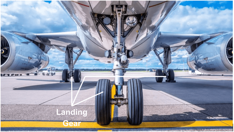
Author : cognitivenavigation

Landing Gear System

Landing Gear System Have you ever looked out of an airplane window and marvelled at the complex machinery supporting the aircraft as it lands gracefully on the runway? The wheels, struts, and gears build up an aircraft’s landing gear system. They play a vital role in ensuring a safe touchdown. Imagine the intricate mechanisms working seamlessly to support the aircraft’s weight during take-off, landing, and taxiing.This comprehensive guide will delve deep into this vital aspect of aviation technology. Let’s demystify the fascinating world of landing gear systems, unravelling their complexities step by step. Discover how these systems are engineered to withstand tremendous forces while providing stability and control. We have it covered, from the different types of landing gear designs to the maintenance practices that keep them operating smoothly. So, prepare to elevate your knowledge and appreciation for the mechanical mastery that keeps planes safely grounded. Introduction to Landing Gear System An essential element of an aircraft, the landing gear system, also known as the undercarriage, assumes the responsibility of carrying the airplane’s weight when it is not in flight. It is the first structure to touch the runway during landing and the last to part ways as the aircraft takes off.At its core, a landing gear system comprises a structure that supports the aircraft while it is on the ground. This structure performs several essential functions, such as bearing the total aircraft weight during ground operations, providing traction, and absorbing the impact during take-off and landing. Types of Landing Gear Systems They normally include a variety of wheel layouts, including conventional, tandem, and tricycle types. Furthermore, landing gear systems can be fixed or retractable. 1. Fixed Landing Gear As the name suggests, the fixed landing gear is permanently attached to the aircraft. It remains extended and exposed, whether the aircraft is on the ground or in the air. Fixed landing gear is simple to repair. It is used on small airplanes and constructed of two wheels that protrude outwards on inclined axles from the front-center part of the fuselage. While fixed landing gear is a simple, low-maintenance, and cost-effective solution, it has some significant downsides. For example, the stationary nature of the landing gear generates constant drag, limiting aerodynamics and reducing fuel economy. 2. Retractable Landing Gear Retractable landing gear is a popular component caught on commercial airliners and high-altitude aircraft. This type of landing equipment can be folded or stowed inside the aircraft while in flight. One of the advantages of retractable landing gear is its ability to reduce drag, enhance aerodynamics, and improve the overall cruising speed and aircraft’s glide distance. Depending on the airplane structure, they can be operated electronically, manually, or hydraulically. The mechanism behind this type of landing gear typically involves a series of gear actuators, gear extensions, pumps, and gear switches. It is worth noticing that retractable landing gear adds weight to the aircraft, which is why they are mainly installed on commercial airliners or gigantic planes that can handle and maintain it. They are more complex and costly when compared with other types of landing gear. 3. Tricycle Landing Gear Tricycle landing gear is the most general type in general aviation airplanes. They are particularly used for small to large-sized ones. They comprise two primary wheels positioned beneath the fuselage, with a third wheel typically located towards the front or nose of the aircraft. While tricycle gear may be slightly heavier when compared to other landing gear types, it offers numerous advantages for smaller aircraft. For instance, it enhances steering capabilities, promotes stability during take-offs and landings, and reduces the risk of ground loops. Fixed tricycle gear often includes fairings installed over each wheel to improve aerodynamics and overall speed. Also, tricycle gear can be retractable. The retractable tricycle gear designs involve the two main wheels retracting into the fuselage or under the wings while the front wheel retracts into the nose. Retractable tricycle gear aids in reducing drag and further enhancing aircraft performance. 4. Tandem Landing Gear The tandem landing gear system is a configuration used in aircraft to provide stability and support during take-off, landing, and taxiing. This system consists of two landing gear units located one behind the other, with the forward unit typically positioned under the fuselage and the rear unit under the tail. The purpose of this arrangement is to distribute the weight of the aircraft evenly across both gear units, ensuring a balanced and stable landing. This configuration also allows for better maneuverability on the ground, as the airplane can pivot around the rear gear unit during taxiing. 5. Conventional Landing Gear This type of landing gear, also known as a taildragger, features two main wheels towards the front of the aircraft and a smaller wheel or tailwheel at the rear. It provides good ground clearance, making it suitable for rough or unimproved runways. 6. Floatplanes and Ski Landing Gear Floatplanes replace traditional wheels with large floats or pontoons, enabling them to take off from and land on water. On the other hand, ski-equipped aircraft swap out traditional wheels for skis, allowing them to land on snow and ice. 7. Bogie Landing Gear Bogie undercarriages are an essential component of an aircraft’s landing gear system. The word “bogie” refers to a set of wheels attached to a framework. It provides support and stability to the aircraft during take-off, landing, and taxiing. They are designed to distribute the aircraft’s weight evenly across multiple wheels, reducing the stress on individual tires and providing better traction and stability on various types of terrain. Commercial airliners typically have multiple bogie undercarriages noticed along the fuselage length, while smaller aircraft may have a single near the center of gravity. The number of wheels in a bogie can also vary, with larger aircraft usually having more wheels for increased stability. Components of a Landing Gear System The landing gear system consists of several components, including Struts Struts, also known as shock absorbers, are critical components that absorb the impact forces during

Aircraft Engines

Aircraft Engines: The Powerhouse of an Aircraft Aircraft engines are the powerhouse behind the incredible ability of airplanes to soar through the skies. These highly complex machines generate the thrust necessary to propel aircraft forward, allowing them to overcome gravity and achieve flight. The Jet Engines and Reciprocating Engines are two main categories of aircraft engines. Let’s start with the first category of aircraft engines: Jet Engine A jet engine operates in compliance with Newton’s third law of motion, which states that “for every action (force), there is an equal and opposite reaction (force).” A jet engine operates in compliance with Newton’s third law of motion, which states that “for every action (force), there is an equal and opposite reaction (force).” In aircraft propulsion, the ‘body’ refers to the atmospheric air that accelerates through the engine. The force necessary for acceleration has an equal effect in the opposite direction on the machine producing it. A jet engine is a reacting engine, generating a thrust and propeller combination. Both drive the aircraft by shoving massive amounts of air backward, one as a low-speed slipstream and the other as a high-speed jet. In this comprehensive writing, we will delve into the inner workings of aircraft jet engines, exploring the different types of jet engines and uncovering the fascinating mechanisms that enable these engines to function. In this comprehensive writing, we will delve into the inner workings of aircraft jet engines, exploring the different types of jet engines and uncovering the fascinating mechanisms that enable these engines to function. Working of Jet Engine-: Step-by-Step Explanation Inlet The first component of an aircraft engine is the inlet. An inlet captures and directs incoming air into the engine. First, in the operation of a jet engine is the air intake. As the aircraft moves forward, the intake scoops in large volumes of air from the atmosphere. Its primary responsibilities are ensuring uniform airflow while minimizing disturbances and pressure losses. They are designed to slow down the oncoming air and compress it – decrease its speed – to make it easier to handle inside the engine. At the front of the engine is a huge fan or compressor that draws in a significant amount of air. It is situated behind the air intake and is the first component to meet incoming air in high-bypass turbofan engines. It is the most common type of jet aircraft in the commercial sector. The fan spins, letting air out around the engine, bypassing the core and providing most of the thrust, making it quiet and energy-saving. The air is pushed into the engine’s core by the fan. Compressor The compressor, often called the heart of an aircraft engine, compresses the incoming air to higher pressures. Compressors are often composed of several stages, each with spinning blades (rotors) and stationary blades. The rotors accelerate the air while the stators slow it down, increasing its pressure. This technique significantly increases air pressure before it enters the combustion chamber.When air is sucked into the engine, it goes through a set of compressor blades. These blades progressively compress the air, increasing its density and pressure. The compression process prepares the air for the combustion stage. Combustion Chamber The magic happens in the combustion chamber. This part creates high-temperature, high-pressure gases by combining compressed air and fuel to ignite the mixture. The engine is driven by the enormous energy released during combustion. After compression, fuel gets injected into the compressed air mixture. The mixture then enters the combustion chamber, where it ignites, which leads to a rapid release of energy. The combustion process generates excessively high temperatures, often exceeding the melting point of the turbine blades. How combustion chamber is protected from high temperatures when it reaches the melting point of structural metal? Two things must happen to keep the chamber from melting. To begin, some air from the pre-combustion airflow is added to form a thin film of air between the hot gas and the chamber. Second, the combustion chamber is a titanium alloy with a ceramic coating. These extremely thin ceramic coatings reduce the material temperature to roughly 300 °C. Titanium combustion chambers are cast, welded together, and coated with ceramic. Turbine and Thrust Generation The turbine draws energy from the high-temperature, high-pressure gases generated during combustion. It is located downstream of the combustion chamber. It includes several revolving blades that are propelled by the expanding gasses as they pass over them. The compressor and additional engine components, like generators and hydraulic pumps, are run by this rotation.As combustion occurs, high-temperature gasses expand and pass through several turbine blades. The expanding gasses power a shaft that is attached to these blades. The energy gets transferred by the gases as they move through the turbine that rotates the turbine blades.The engine may run continuously because of the connection between the rotating turbine shaft and the compressor seen at the front of the engine. Moreover, depending on the engine type, the turbine shaft is linked to the fan or propeller of the engine. The thrust is required to move the aircraft forward and is produced by the fan rotating or propeller. For turbofan engines, around 80% of thrust comes from the fan, while 20% from the core engine. Exhaust After passing through the turbine, the exhaust gases exit the engine through the nozzle. The final stage of the jet engine operation involves the removal of exhaust gases. These gases flee the engine through a carefully designed nozzle, which helps maximize thrust efficiency. The expelled gases create a powerful jet stream, propelling the aircraft forward by Newton’s Third Law. It is 100% for turbojet engines. For turbofan, this is 20%, and for turboprop, it happens to have a negligible effect on producing forward movement force. Type of Jet Engines Turboprop Engine The turboprop engine is a type of turbojet engine. It is connected to the aircraft’s propeller by a gearing system. Most of the thrust gets produced by the turbojet-driven fan blades located at the

AIXM & ARINC 424 powered Aeronautical Modules

AIXM and ARINC 424 powered Aeronautical Modules The Challenge Reliance on static PDF and HTML formats for aeronautical information pose significant challenge, particularly in the absence of digital aeronautical data. This limitation hampers the creation of AIXM & ARINC 424 powered Aeronautical Modules, affecting real-time updates and interactivity. Such static formats do not provide the necessary dynamic information crucial for efficient flight planning and navigation, posing challenges for aviation professionals who require timely data for safety and decision-making. The consequence of this reliance on previous formats extends to a hindrance in the integration of digital aeronautical data with modern flight operational systems. This limitation stifles the progress of aviation technology, preventing it from creation of digitalized Aeronautical modules such as eTOD, AMDB, eCharting etc, aligning with global standards like AIXM and ARINC 424. To overcome these challenges and enhance operational effectiveness, there is a need to transition towards comprehensive digital aeronautical data formats. This shift ensures accuracy, timeliness, and the seamless integration of critical information, bringing the nation’s aviation industry in line with global technological standards. Our Role Cognitive Navigation’s Aeronautical Expertise played a crucial role in transforming India’s aeronautical information system. Recognizing the limitations of static PDF and HTML formats, we initiated a comprehensive solution. Firstly, we extracted and converted the existing static aeronautical data into dynamic digital formats, adopting the AIXM standard—a globally recognized model for aeronautical information exchange. This transition enabled real-time updates, providing Aviation professional stakeholders with accurate and timely information crucial for flight planning and safety. In parallel, Cognitive’s GIS Specialists spearheaded the development of advanced digital aeronautical maps. These maps offered improved readability and interactivity, addressing the challenges posed by static formats. By integrating cutting-edge technology and adhering to regulatory and industrial standards, Cognitive Navigation ensured that the digital maps met the highest industry benchmarks. Furthermore, it contributed to the creation of electronic Terrain and Obstacle Databases (eTOD) and Aeronautical Mapping Databases (AMDB), aligning with regulatory guidelines. This holistic approach not only modernized India’s aeronautical data presentation but also facilitated seamless integration into the global aviation ecosystem. The expertise provided by Cognitive Navigation significantly enhanced the efficiency, accuracy, and safety of India’s flight planning and navigation processes, marking a transformative milestone in the country’s aeronautical information management. Our Expertise Aeronautical Data Analysis Information gathering and sourcing Aeronautical Information Management (AIM) Geographic Information System (GIS) service Aeronautical Information Service (AIS) Process development Root Cause Analysis Research and Development

Aeronautical Maps – Enhanced Digitalization

Aeronautical Maps – enhanced digitalization The Challenge In the aviation domain, the reliance on aeronautical maps by operational stakeholders is indispensable for crafting efficient and secure flight routes. However, the exponential growth in aeronautical data has given rise to a significant challenge. Traditional static maps, while rich in information about airspace structure, navigation aids, terrain, and obstacles, struggle to maintain information priority standards, useability, interactiveness, regulatory standards and succumb to information clutter. This poses a real concern for aviation professionals, as the sheer volume of data presented in a fixed format can be overwhelming, making it difficult to discern critical details amidst the complexity. To address this challenge, there is a growing need for an interactive Aeronautical digitalized map. Such a dynamic solution would empower users, to selectively visualize pertinent information. By offering a customizable interface, this digitalized map would enhance clarity and streamline the interpretation of extensive aeronautical data. This transformative approach not only mitigates the challenges posed by static maps but also presents an opportunity to revolutionize the way operational stakeholders engage with and extract meaningful insights from the ever-expanding realm of aeronautical information, ultimately leading to safer and more efficient flight planning. Our Role Cognitive Navigation’s expertise in aviation domain demonstrated its commitment to excellence by providing Aeronautical and analytical expertise throughout the development of internationally competitive interactive aeronautical digital maps. We conducted in-depth analysis of complex aeronautical data to ensure accuracy and adherence to regulatory and industry standards. Our team spearheaded the creation of new functionalities, introducing innovative features that enhanced user experience and flight planning efficiency.Additionally, we generated new ideas to address challenges such as data clutter and readability issues. The team proposed solutions to optimize map displays, streamline information presentation, and improve overall usability. Cognitive Navigation’s GIS (Geographic Information System) specialists proved crucial in the development process. The team harnessed advanced GIS technologies to organize, analyse, and visualize spatial data effectively. This expertise facilitated the seamless integration of aeronautical maps with other Flight Operational systems and provided a foundation for the creation of adynamic, interactive mapping platform. By combining analytical prowess, innovative thinking, and GIS expertise, Cognitive Navigation’s Aeronautical team not only met but exceeded the needs. The resulting internationally competitive digital aeronautical maps set a new standard in precision, real-time updates, and user-friendly functionality for global flight planning. Our Expertise Aeronautical Data Analysis Information gathering and sourcing Geographic Information System (GIS) service Aeronautical Information Service Process development Root Cause Analysis Research and Development

Scroll to top